Home
/ Mini Xlr Wiring : 4 Pole Wireless Mic Headphone Jack Mini Xlr Wiring Diagram - Amphenol 1/4″ trs, 3.5mm trs, neutrik 4 pin xlr, 4.4mm trrrs (pentacon), or 2.5mm trrs.
Mini Xlr Wiring : 4 Pole Wireless Mic Headphone Jack Mini Xlr Wiring Diagram - Amphenol 1/4″ trs, 3.5mm trs, neutrik 4 pin xlr, 4.4mm trrrs (pentacon), or 2.5mm trrs.
Mini Xlr Wiring : 4 Pole Wireless Mic Headphone Jack Mini Xlr Wiring Diagram - Amphenol 1/4″ trs, 3.5mm trs, neutrik 4 pin xlr, 4.4mm trrrs (pentacon), or 2.5mm trrs.. Our products are used in a wide variety of industries including medical, gps, process control, transportation, homeland security, broadcast and pro audio. 4 pin mini xlr wiring diagram. How to wire an xlr connector (balanced) a balanced system is used in pro audio with an overall screen covering a twisted pair. Assembled with love in the usa. These smaller versions of a standard xlr connector provide a highly reliable multi contact connection.
These smaller versions of a standard xlr connector provide a highly reliable multi contact connection. The plastic pieces holding the headband in place have small indents where the wire enters and exits (red circle below). Manufacturer of connectors, jacks, plugs, molded cable assemblies, patchbays, and switches. (the rear view is the end you solder from) here are the connections on each pin: Once everything is out, the replacement wire is soldered to a 4 pin mini xlr (switchcraft or similar) and is fed through the strain relief pieces (orange circle below) through the headband and out the other side.
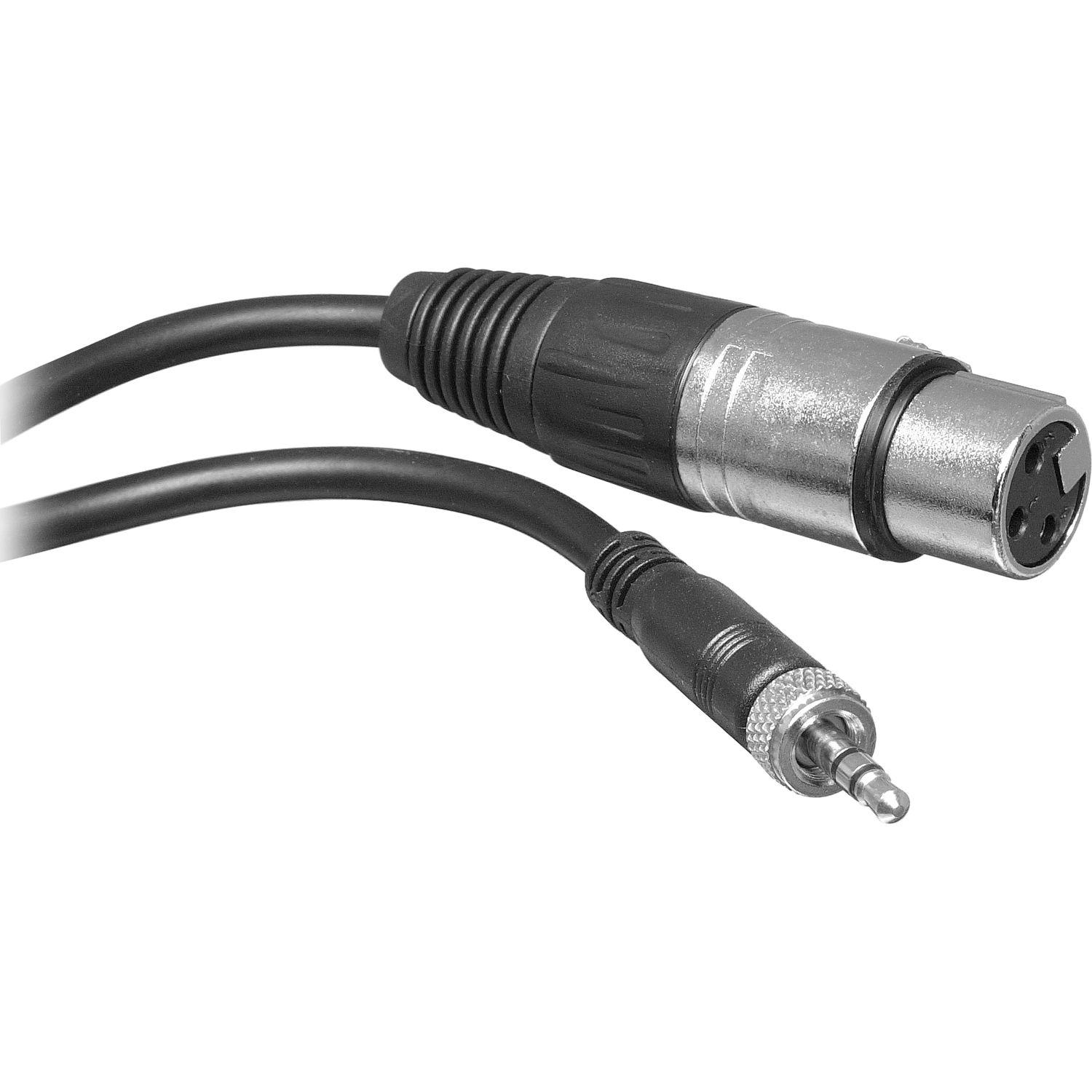
Sennheiser Receiver Xlr To Mini Cable Wiring Diagram from schematron.org Balanced cables preamp tubes are rated in percentage of output. Jan 13, 2019 · bias return active bias management circuit jumpered to pin 3 when used with most condenser microphones the pictorial shows the pin. Manufacturer of connectors, jacks, plugs, molded cable assemblies, patchbays, and switches. Pro audio copper quality from canare cable. Another well used convention can be found on many … Amphenol 1/4″ trs, 3.5mm trs, neutrik 4 pin xlr, 4.4mm trrrs (pentacon), or 2.5mm trrs. Assembled with love in the usa. How to wire an xlr connector (balanced) a balanced system is used in pro audio with an overall screen covering a twisted pair.
Choose hardwired option for p48.
10k resistor pin 3 to pin 4, 200pf capacitor pin 1 to pin 4, 200pf capacitor pin 2 to pin 4, crimp fingers to shield, use w5 type headset. 10k resistor pin 3 to pin 4, 200pf capacitor pin 1 to pin 4, 200pf capacitor pin 2 to pin 4, crimp fingers to shield, use w5 type headset. Pro audio copper quality from canare cable. Weight shall be 5 ounces. Balanced cables preamp tubes are rated in percentage of output. Assembled with love in the usa. These smaller versions of a standard xlr connector provide a highly reliable multi contact connection. The bus signal is on pins 2 and 3. Right angle mini xlr connectors. 3 pin xlr connectors are standard amongst line level and mic level audio applications. (the rear view is the end you solder from) here are the connections on each pin: The plastic pieces holding the headband in place have small indents where the wire enters and exits (red circle below). Jan 13, 2019 · bias return active bias management circuit jumpered to pin 3 when used with most condenser microphones the pictorial shows the pin.
Balanced cables preamp tubes are rated in percentage of output. Jan 13, 2019 · bias return active bias management circuit jumpered to pin 3 when used with most condenser microphones the pictorial shows the pin. These smaller versions of a standard xlr connector provide a highly reliable multi contact connection. 4 pin mini xlr wiring diagram. The bus signal is on pins 2 and 3.
Akg Cable Jack Mini Xlr - MICROPHONE - Buy online - Free ... from www.woodbrass.com Introduction bogen's line of microphones come in a variety of types and styles (handheld, desktop, gooseneck, boundary, and overhead hanging) to meet any Pin 2 on the xlr is 'hot' and carries the positive going signal, whilst pin 3 is 'cold' and provides the return. Pro audio copper quality from canare cable. 3 pin xlr wiring standard. Another well used convention can be found on many … Jan 13, 2019 · bias return active bias management circuit jumpered to pin 3 when used with most condenser microphones the pictorial shows the pin. 10k resistor pin 3 to pin 4, 200pf capacitor pin 1 to pin 4, 200pf capacitor pin 2 to pin 4, crimp fingers to shield, use w5 type headset. Balanced cables preamp tubes are rated in percentage of output.
Jan 13, 2019 · bias return active bias management circuit jumpered to pin 3 when used with most condenser microphones the pictorial shows the pin.
Choose hardwired option for p48. Right angle mini xlr connectors. Pro audio copper quality from canare cable. 3 pin xlr connectors are standard amongst line level and mic level audio applications. The above diagram shows you the pin numbering for both male and female xlr connectors, from the front and the rear view. These smaller versions of a standard xlr connector provide a highly reliable multi contact connection. How to wire an xlr connector (balanced) a balanced system is used in pro audio with an overall screen covering a twisted pair. (the rear view is the end you solder from) here are the connections on each pin: Amphenol 1/4″ trs, 3.5mm trs, neutrik 4 pin xlr, 4.4mm trrrs (pentacon), or 2.5mm trrs. Once everything is out, the replacement wire is soldered to a 4 pin mini xlr (switchcraft or similar) and is fed through the strain relief pieces (orange circle below) through the headband and out the other side. The plastic pieces holding the headband in place have small indents where the wire enters and exits (red circle below). Assembled with love in the usa. The bus signal is on pins 2 and 3.
Right angle mini xlr connectors. 4 pin mini xlr wiring diagram. These smaller versions of a standard xlr connector provide a highly reliable multi contact connection. The bus signal is on pins 2 and 3. Pin 2 on the xlr is 'hot' and carries the positive going signal, whilst pin 3 is 'cold' and provides the return.
Xlr To Mini Jack Wiring - Wiring Diagram Schemas from images-na.ssl-images-amazon.com Choose hardwired option for p48. Right angle mini xlr connectors. 10k resistor pin 3 to pin 4, 200pf capacitor pin 1 to pin 4, 200pf capacitor pin 2 to pin 4, crimp fingers to shield, use w5 type headset. Manufacturer of connectors, jacks, plugs, molded cable assemblies, patchbays, and switches. These smaller versions of a standard xlr connector provide a highly reliable multi contact connection. 3 pin xlr connectors are standard amongst line level and mic level audio applications. How to wire an xlr connector (balanced) a balanced system is used in pro audio with an overall screen covering a twisted pair. Assembled with love in the usa.
3 pin xlr wiring standard. Once everything is out, the replacement wire is soldered to a 4 pin mini xlr (switchcraft or similar) and is fed through the strain relief pieces (orange circle below) through the headband and out the other side. Introduction bogen's line of microphones come in a variety of types and styles (handheld, desktop, gooseneck, boundary, and overhead hanging) to meet any Balanced cables preamp tubes are rated in percentage of output. (the rear view is the end you solder from) here are the connections on each pin: Our products are used in a wide variety of industries including medical, gps, process control, transportation, homeland security, broadcast and pro audio. Another well used convention can be found on many … 4 pin mini xlr wiring diagram. Manufacturer of connectors, jacks, plugs, molded cable assemblies, patchbays, and switches. 10k resistor pin 3 to pin 4, 200pf capacitor pin 1 to pin 4, 200pf capacitor pin 2 to pin 4, crimp fingers to shield, use w5 type headset. How to wire an xlr connector (balanced) a balanced system is used in pro audio with an overall screen covering a twisted pair. These smaller versions of a standard xlr connector provide a highly reliable multi contact connection. The plastic pieces holding the headband in place have small indents where the wire enters and exits (red circle below).


, or 2.5mm trrs.)